-
 support@minemaxx.com
-
 0086-311-87833311
 NO.8 JIHENG STREET,QIAOXI DISTRICT,SHIJIAZHUANG,HEBEI,CHINA
1 月 . 25, 2025 20:14
Back to list
slurry pump diagram
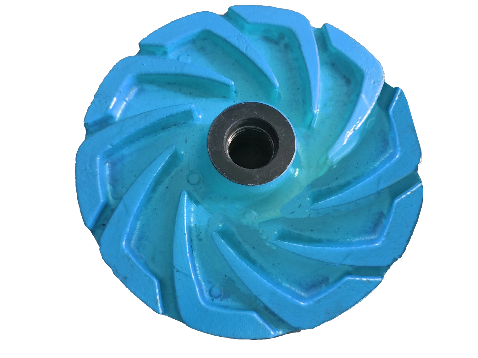
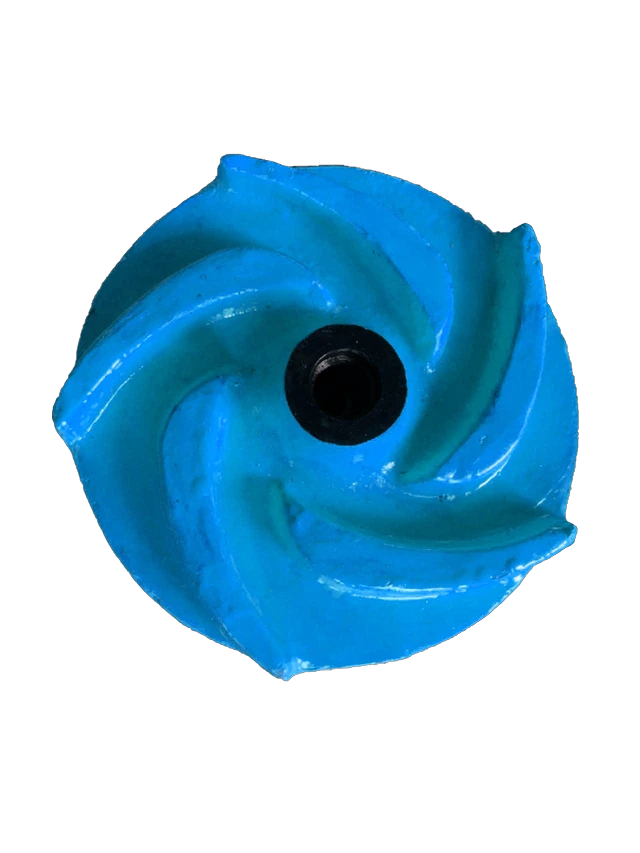
Understanding the blueprint of a slurry pump is essential for anyone involved in handling or processing abrasive materials. A slurry pump diagram is not just a blueprint; it's a critical knowledge base that enhances operational efficiency, pump longevity, and system safety. This article dives into the intricacies of slurry pump diagrams with insights from industry professionals, providing actionable knowledge backed by real-world experience.
Seals and bearings are additional vital components depicted in slurry pump diagrams. Seals prevent slurry leakage and protect the pump's internal systems from contaminants, while bearings support the shaft, ensuring smooth rotational motion. Properly maintaining these components is paramount; neglected seals can lead to catastrophic failures and increased operational costs due to leakage and potential system contamination. Trustworthy maintenance schedules and the use of quality materials for these components are a mark of expert handling. Real-world experience emphasizes the collaborative role of engineers and operators in interpreting and implementing slurry pump diagrams for improved serviceability and reduced downtime. Industry insiders advocate for training operational staff to understand these diagrams, ensuring they possess the expertise to identify potential issues promptly. This collaborative approach not only boosts pump longevity but also solidifies an organization’s authoritative stance in effective slurry management. In conclusion, delving into a slurry pump diagram is more than identifying parts and connections. It's about leveraging expert insights to optimize system performance, ensuring the resilience and efficiency of the pump, and showcasing a commitment to operational excellence. Such comprehensive knowledge serves as a cornerstone in achieving a seamless flow of operations, where reliability and trustworthiness in pump performance become a benchmark for industry success.


Seals and bearings are additional vital components depicted in slurry pump diagrams. Seals prevent slurry leakage and protect the pump's internal systems from contaminants, while bearings support the shaft, ensuring smooth rotational motion. Properly maintaining these components is paramount; neglected seals can lead to catastrophic failures and increased operational costs due to leakage and potential system contamination. Trustworthy maintenance schedules and the use of quality materials for these components are a mark of expert handling. Real-world experience emphasizes the collaborative role of engineers and operators in interpreting and implementing slurry pump diagrams for improved serviceability and reduced downtime. Industry insiders advocate for training operational staff to understand these diagrams, ensuring they possess the expertise to identify potential issues promptly. This collaborative approach not only boosts pump longevity but also solidifies an organization’s authoritative stance in effective slurry management. In conclusion, delving into a slurry pump diagram is more than identifying parts and connections. It's about leveraging expert insights to optimize system performance, ensuring the resilience and efficiency of the pump, and showcasing a commitment to operational excellence. Such comprehensive knowledge serves as a cornerstone in achieving a seamless flow of operations, where reliability and trustworthiness in pump performance become a benchmark for industry success.
Previous:
Next:
Latest news
-
Wet Parts for Optimal PerformanceNewsOct.10,2024
-
Vertical Pump Centrifugal SolutionsNewsOct.10,2024
-
Top Slurry Pump ManufacturersNewsOct.10,2024
-
The Ultimate Guide to Centrifugal Pump for SlurryNewsOct.10,2024
-
Pump Bearing Types for Optimal PerformanceNewsOct.10,2024
-
A Guide to Top Slurry Pump SuppliersNewsOct.10,2024
-
Slurry Pump Parts for Optimal PerformanceNewsSep.25,2024

